How to guideUpdated: April 12th, 2021
Mechanical Assembly Checklist
Overview
The mechanical assembly checklist should be used as a final check once the system is assembled.
Use the following checks to ensure that your system is assembled correctly.
General assembly
1. Extrusions |
Extrusions are assembled according to CAD design.
|
|
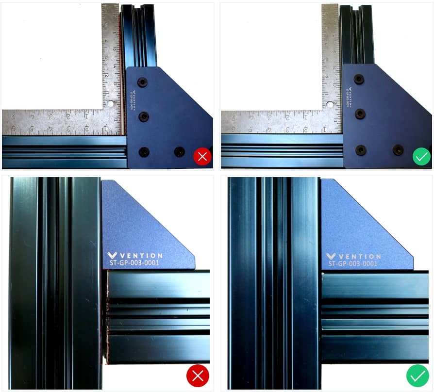
2. Gussets |
High-precision (HP) and general-precision (GP) gussets are installed in correct locations. | |
3. Plates |
Assembly plates are properly mounted; no fasteners are missing. | |
4. Frame |
Base frame can support more than enough weight.
For details, see the assembly guide . |
 |
5. Screws |
Screws are securely tightened.
For details, see the anti-vibration products guide . |
|
6. Level |
System is leveled.
|
|
7. Cables and tubes |
Cables and tubes are sufficiently long and run along clear paths.
For details, see the cable management guide . |
|
8. Hinges |
Hinges move smoothly. | |
9. Safety interlock |
Safety interlocks are adjusted and fully engaged. | |
10. Custom parts |
Custom parts are deburred and have no sharp edges. |
Rack and pinion
11. Rack spacing |
Gear rack sections are properly joined.
For details, see the rack and pinion actuator guide . |
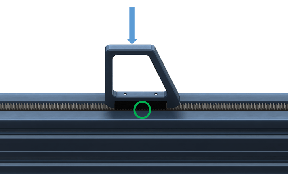 |
12. End-stop brackets |
End sensor brackets are tightened on rack. | |
13. Housing |
Bearings and/or rollers are securely mounted on housing. |
Alignment
14. Rails |
Linear rails are leveled and parallel. Rail brackets are securely tightened on extrusions. Gantry moves fluidly on the rails, traveling from end to end without any resistance. For details, see the linear axis alignment guide . |
|
15. Shaft |
If system has butt-jointed rails: Butt-joints have no chamfer, gaps, or misalignment.
|
|
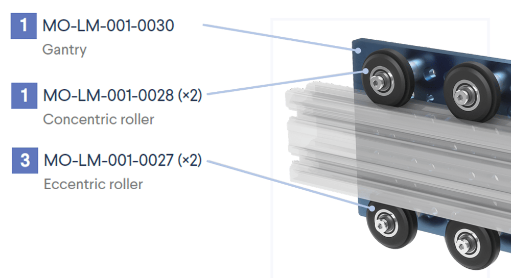
16. Roller wheels |
Eccentric rollers are all on one side and properly adjusted; concentric rollers are all on the opposite side.
For details, see the linear guides datasheet . |
 |
Lubrication and maintenance
Find step-by-step instructions for these components in the maintenance guide.
17. Linear ball bearings |
Installation: Ball bearings lubricated.
Maintenance plan: Linear ball bearings lubricated once a year or after every 100 km of travel, whichever comes first. | 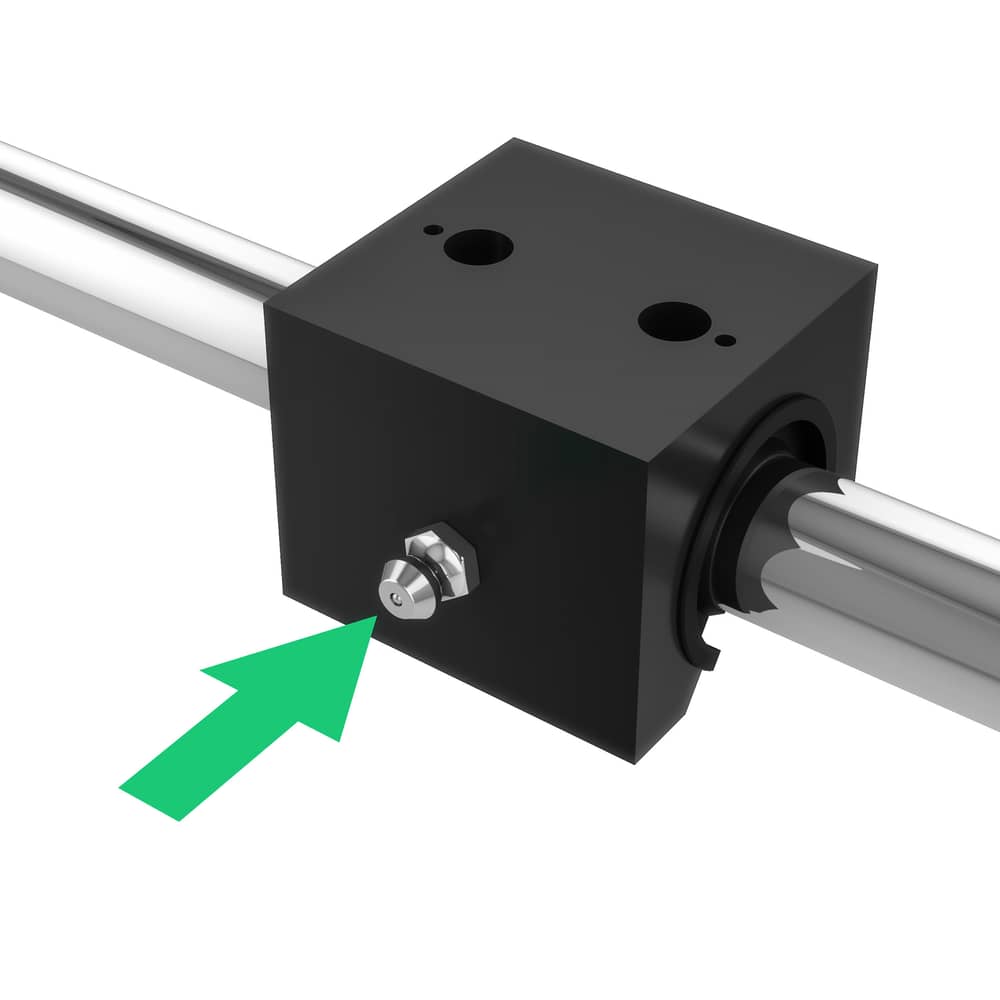 |
18. Plain bearings |
Installation (recommended): Shaft cleaned with 3-in-1 oil.
No lubrication required for installation or maintenance. | 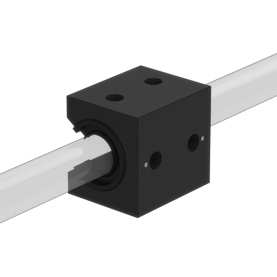 |
19. Ball screws |
Installation: Ball screws lubricated.
Maintenance plan: Ball screws lubricated every six months or after 500,000 revolutions, whichever comes first. | 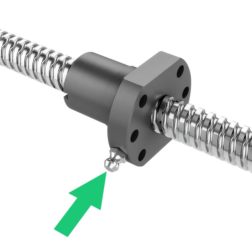 |
20. Rack and pinion |
Installation: Gear racks lubricated.
Maintenance plan: Gear racks lubricated every six months or after 500,000 revolutions, whichever comes first. | 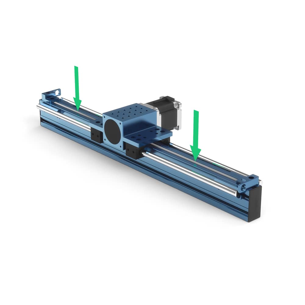 |
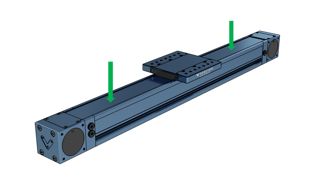
21. Enclosed timing belt actuator |
Installation: N/A (ships pre-lubricated).
Maintenance plan: Bearings and cover strips lubricated once a year or after every 100 km of travel, whichever comes first. | 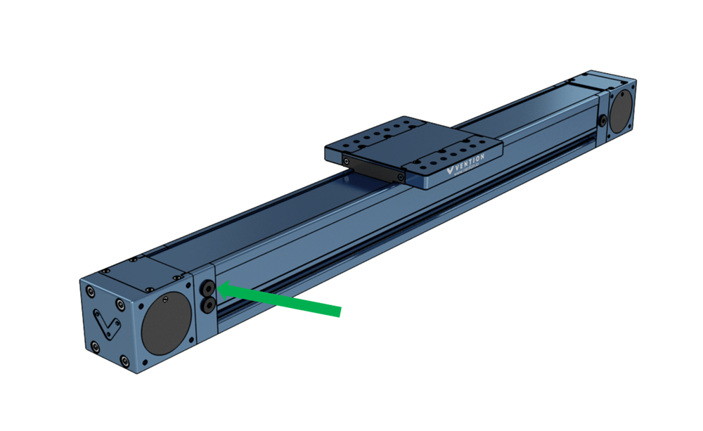
|
22. Rotary actuator |
Installation: N/A (ships pre-lubricated).
Maintenance plan: Gears lubricated every six months or after 10,000 revolutions, whichever comes first. | 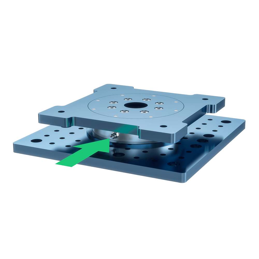 |
Sensors
23. End-stop sensor |
If using an actuator: End-stop sensors are functioning (to detect when gantry reaches end of travel). | |
24. End-stop bumper |
Sensor has sufficient clearance from plate at end-stop position.
| |
25. Sensor mounting |
Sensors have enough clearance and are not intercepted by the movement of other components. |
Motors
26. Motor |
Before installation: Shaft has key installed on it. | |
27. Power transmission devices |
Before installation: Design follows proper order of motor, gearbox, and brake.
If using a gearbox: The input clamping mechanism is properly secured through ports on the gearbox's side. |